Matching Load Requirements: The Secret to Choosing Control Transformers
Control transformers play a pivotal role in electrical systems, facilitating the conversion of higher voltages into lower, safer voltages to regulate electrical equipment. This article delves into the intricacies of control transformers, emphasizing their function in voltage reduction for control purposes. It also highlights key considerations such as dual voltage connections, inrush currents, and full-load currents, and outlines a four-step process for selecting the appropriate control transformer.
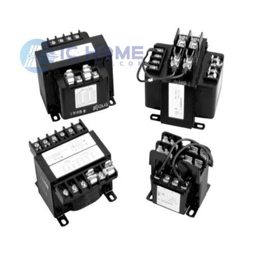
The Purpose of Control Transformers
Control transformers are indispensable for reducing higher voltages to lower, safer levels, enabling the control of various electrical devices. For instance, a 480-volt motor can be activated or deactivated using a 24-volt pushbutton connected to the secondary winding of a control transformer with a primary voltage of 480 volts. Clearly, a 24-volt circuit presents significantly fewer hazards than a 480-volt circuit. The primary function of control transformers is to provide power for operating contactors, motor starters, pilot lights, solenoids, and other control devices.
Dual Voltage Connections
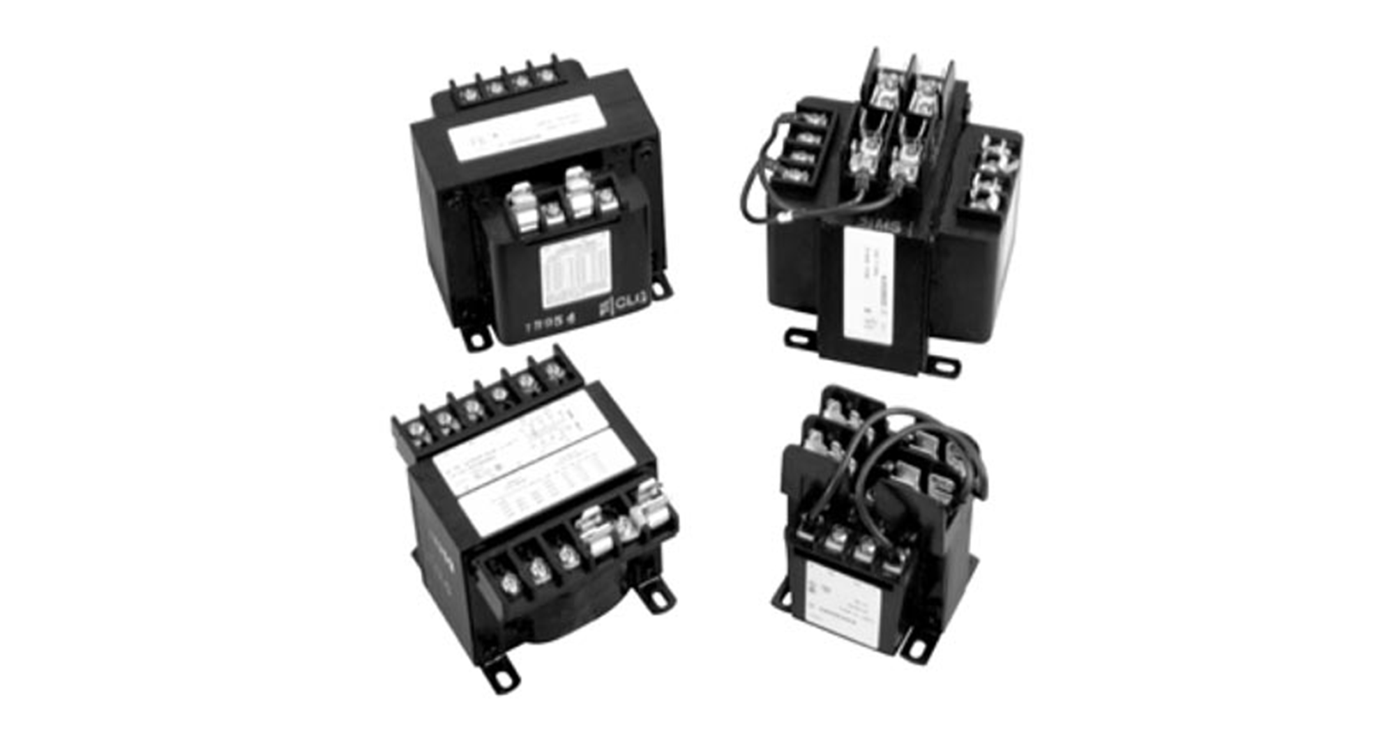
The power demands of control devices are generally modest. Consequently, control transformers typically have relatively small KVA ratings, often less than 1 KVA. The following figure illustrates a typical control transformer. In most control transformers, the H winding is configured for dual voltage operation – commonly 240 x 480 volts for industrial applications and 120 x 240 volts for residential applications. The X winding is usually rated at 120 volts for industrial use and 24 volts for residential applications.
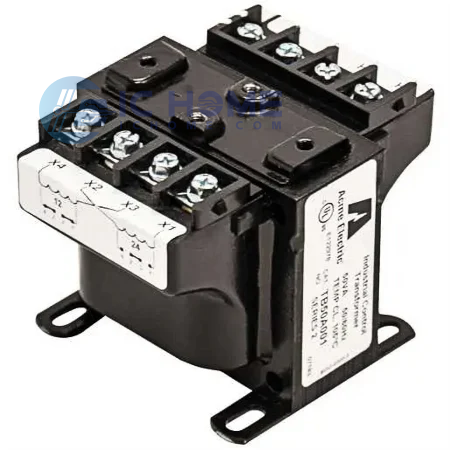
The arrangement of the X winding connections allows for voltage adjustments by simply connecting jumpers between the terminals. To obtain a lower voltage, jumpers are connected between the X1 and X3 terminals, and another pair between the X2 and X4 terminals, effectively connecting the X windings in parallel. Conversely, to achieve a higher voltage, both jumpers are connected between the X2 and X3 terminals, connecting the windings in series.
Inrush Current
Ohm's Law stipulates that the voltage drop across a resistor is directly proportional to the current flowing through it. Similarly, in a transformer, the voltage drop across the secondary winding resistance increases with the load current. However, inductors, which are prevalent in control circuits, exhibit a unique characteristic. Due to the counter electromotive force (CEMF) induced in the coil, inductors initially offer minimal resistance to current flow. As a result, when a control transformer supplies an inductive load, the initial inrush current can be significantly higher – often ten times or more – than the normal operating or full-load current.
Control transformers are specifically designed to accommodate these high inrush currents without excessive voltage drops, ensuring reliable operation of the connected devices. It is imperative that the secondary voltage does not fall below 85% of its rated value during inrush current conditions, as insufficient voltage may compromise device functionality.
Full-Load Current
The apparent power rating of a control transformer, expressed in volt-amperes (VA), determines its full-load current capacity. For instance, a 250 VA, 240-120 volt control transformer can deliver a continuous output of 250 VA, equivalent to 2.08 amperes at 120 volts. However, it can also handle transient inrush currents of up to 18 amperes without experiencing excessive voltage drops. It's important to note that these inrush currents are typically short-lived, lasting only a few tens of milliseconds.
The magnitude of the inrush current directly influences the voltage drop across the secondary winding, consequently affecting the output voltage. For example, a transformer might deliver 200 VA while maintaining 90% of its rated secondary voltage, but it could also supply 260 VA at 85% of rated voltage. If the transformer's full-load current rating is adequate but its inrush current capacity is insufficient, the secondary voltage drop may be excessive, compromising the operation of the connected load.
Selecting the Appropriate Control Transformer
To choose the correct size of control transformer, both inrush current and full-load current must be considered. Insufficient inrush capacity can lead to excessive voltage drops, while inadequate full-load current ratings may cause the transformer to overheat and fail prematurely. Follow these steps to determine the appropriate size:
Calculate Total Inrush VA: Sum the inrush VA ratings of all devices that will be simultaneously activated.
Determine Total Working VA: Calculate the combined working VA of all devices when the maximum inrush VA is required.
Select Transformer: Choose a transformer from the specification sheet with a sufficient inrush VA rating to accommodate the total inrush VA calculated in step 2.
Verify Full-Load Capacity: Ensure that the transformer's full-load VA rating is sufficient to handle the combined working VA of all simultaneously activated devices.
Understanding Control Transformers
Control transformers play a vital role in electrical systems, ensuring the safe and reliable operation of controlled electrical equipment. By comprehending the principles of control transformer operation, selection, and sizing, engineers and technicians can design and maintain efficient and reliable electrical systems.
If you need a control transformer, you can contact ICHOME.

